
Revit Case Study: Saving 1,000+ Hours with Dynamo, Revit API & Civil 3D

The Sevastopol Theatre of Opera & Ballet
There are 2 parts to this story:
Model Automation with Dynamo
Drawing Production Automation with C#
“Note: While the details of the scripts are protected under an NDA, I’m able to share the workflow and the results achieved through their implementation.”
Model Automation with Dynamo
The Sevastopol Theatre of Opera & Ballet features a dynamic, flowing façade that wraps continuously around the upper volume of the building. A distinct horizontal division line runs along the facade, visually splitting the surface into two separate ribbons—an upper and a lower band with a split in the middle—that together form a unified wave-like expression. These bands gently curve and shift along the building’s perimeter, giving the illusion of motion and softness across a rigid structural core.
U-kon Engineering supplies rear-ventilated façade support systems in aluminium and stainless steel and maintains an in-house design bureau that helps architects and engineers detail those systems. For the Sevastopol Theatre project they were the façade-system vendor and technical partner—responsible for verifying the support hardware, reviewing our models, and issuing the final fabrication and assembly drawings.
U-kon Engineering reached out after their Canadian representative—who happens to be one of my clients—shared how our Revit-automation workflows had turned weeks of modelling into hours. U-kon’s own forecast for the Sevastopol façade showed:
Subsystem modelling: ≈ 3 months of conventional, manual Revit work
Fabrication & assembly drawings: ≈ 7 additional months
That put the total effort at roughly 10 months, while the project budget covered only 7 months. Automating the workflow was therefore essential to bridge the three-month gap without increasing costs.
Concept
They first planned the façade as a grid of square panels—simple to model, but too stiff for the theatre’s flowing shape. Squares created visible “steps” wherever the wall curved, breaking the wave effect. Switching to triangles solved it: triangles can follow any curve smoothly, keep panel sizes flexible, and maintain a clean, continuous wave. The conversion was straightforward—we just split each square diagonally, then trimmed away any extra triangles to follow the wave’s outline.

First Concept of the Facade

Triangulated Concept of the Facade
Background
What looks like a single fluid surface is, in reality, a kit-of-parts of 2,300+ triangular panels—and no two triangles share the same geometry or orientation. In a traditional Revit workflow that means:
2,300+ unique panel families or instances to place, align, and parameter-check,
2,300+ individual sets of shop-drawing dimensions and tags,
2,300+ opportunities for human error every time the architect adjusted the underlying form.
But the real time sink isn’t the panels themselves; it’s the sub-structure that holds each one in space.
Every triangle requires a mini “sandwich” of hardware:
Two horizontal carrier profiles that run the full width of the panel,
Four brackets that hold the panel along the length of the horizontal profiles,
Two vertical mullion stands that bolt through those profiles,
Three proprietary brackets per panel that fix back to the curved steel frame wrapping the building.
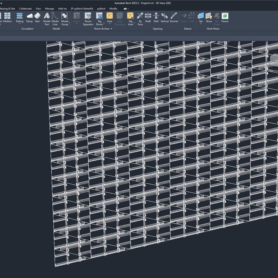
Subsystem of the Facade

Curved Steel Frame
Multiply that micro-assembly by 2,300+ and you have 30,000+ subsystem components—each with its own coordinates, clearances, and fastener details that must remain perfectly synchronized as the façade undulates around corners and changes pitch.
In manual Revit:
Placing and constraining those parts would consume hundreds of labor hours.
Any tweak to the base surface would set off a cascade of re-alignments, deleted constraints, and re-dimensioning.
Generating clean shop drawings would involve endless sheet setup, tagging, and QA passes.
In short, the combination of unique geometry + high part count + strict hardware logic is exactly the scenario where traditional click-based modeling breaks down—and where custom automation becomes the only practical path to accuracy and speed.
Dynamo
The Proof of Concept: Adaptive Components, Dynamo, Revit and Civil 3D
Adaptive Family
Before jumping into full automation, I first developed a triangular adaptive point family in Revit, representing both the panel and its attached subsystem. This allowed me to parametrize the entire assembly—profiles, stands, and brackets—based on three adaptive points. But there was a catch: with over 2,300 uniquely shaped triangles, correct point sequencing and orientation became critical. A single misordered point could flip the panel, reverse its bracket layout, or break the adaptive family.
Dynamo for Revit
To solve this, I created a Dynamo script in Revit to extract:
The triangle panel grid,
The geometry of each panel (converted to solids),
And ultimately, the XYZ coordinates of each triangle’s three corners.
These coordinates were then exported to CSV format, creating a raw dataset of triangle point geometry.
Dynamo for Civil 3D
At this stage, I switched to Civil 3D to pre-process and organize the data. Civil 3D gave me the flexibility to visually inspect, align, and reorder the points spatially—something that would be tedious and error-prone inside Revit. From the CSV data, I reconstructed the triangles with Dynamo, then worked through the logic to redefine the point order consistently across the entire façade.
This part of the process—an orchestration between Civil 3D and Dynamo—took a few hours but was essential. Without it, the adaptive components would have been misaligned or mirrored incorrectly due to inconsistent point sequences, especially around the 90-degree bends of the building’s geometry.
The theatre’s façade wraps around the building with a sharp 90-degree bend. As a result, the point order flipped depending on the façade’s direction:
Panels facing one axis sequenced logically left-to-right
But after the corner, that sequence broke and reversed, causing misaligned adaptive family placement if left untreated.
I had to build logic—both geometric and rule-based—to detect these turns and adjust point indexing accordingly.

The Face of the Facade
Dynamo for Revit
Once the base points were properly sequenced, I returned to Dynamo in Revit and developed a script to read the cleaned point sets, assign them to the adaptive subsystem family, and place each instance with the correct orientation across the entire model.
To handle occasional orientation mismatches—where some families were placed 180 degrees off—I added a custom flip parameter to the adaptive family. This gave me the flexibility to mirror any misaligned instance without re-running the script.
As part of this refinement, I restructured the Dynamo script to place the top and bottom triangles (originally derived from split squares) as separate families. During testing, I noticed that all the top triangles were being placed mirrored due to point orientation. Since they were placed as a distinct family type, it was easy to isolate them in Revit, select them all, and use the flip parameter to instantly correct their orientation—everything snapped into place perfectly.
This pipeline—Revit → Dynamo → CSV → Civil 3D → back to Revit—gave me the accuracy, efficiency, and control needed to deploy the subsystem seamlessly across 2,300+ unique panels, all while preserving the curved continuity, and complexity of the façade.
The Main Advantages
The best part was that because everything was built using a single adaptive family, any design change—whether structural, geometric, or visual—could be made directly within the family itself. Once updated, I could simply reload the family into the project, and all 2,300+ instances of the subsystem across the model would update instantly.
This meant we could fine-tune bracket geometry, adjust profile dimensions, or modify connector positions without re-running the script or repositioning anything manually. It gave us a level of control and flexibility that would’ve been impossible in a traditional modeling workflow.
One of the biggest advantages of this workflow was adaptability. Traditional Revit workflows fall apart the moment major design changes occur—especially with unique geometry like this façade. But with our automated setup, design iteration became effortless.
At one point during the project, the architect decided to shift several sections of the façade geometry. That would normally mean days—if not weeks—of rework, manually repositioning every component of the subsystem.
Instead, they simply sent me the updated triangle grid. Within about an hour, I regenerated the entire façade subsystem:
Reprocessed the new geometry
Resequenced the points
Redeployed the adaptive families
And produced a fully updated model with perfectly aligned, correctly oriented components
No manual adjustment. No rework. Just a clean, automated reset—allowing the design team to explore changes without being held back by modeling overhead.
The Result
The entire concept for the automation workflow was developed in just one day. Within one week, we had a fully functional system that could generate and deploy the façade subsystem automatically. The complete Revit model—including all components, placement logic, and QA/QC—was finalized in one month.
Had we followed a conventional, manual modelling process, this would have taken at least three months.
Metrics:
Time saved: ≈ 2 months
Error rate: near zero
Scalability: The workflow is now reusable on future projects with similar complexity
Drawing Production Automation with C#

Assembly Drawings
Now we were getting to the fun part—drawing automation. Once the full model and façade subsystem were complete and fully automated, we moved on to the next challenge: producing over 1,000 detailed section drawings for fabrication and assembly. Doing this manually would have overwhelmed the remaining project timeline. Here is a brief overview, since this post is already getting long:
Step 1: Identify What Needed to Be Automated
We began by sitting down with the team to define exactly what the drawing sets required—the structure, consistency, and control. The goal was to produce precise, controlled, fabrication-ready documentation that could be issued without endless cleanup.
Basically, they needed 4 Scripts:
Automated generation of section views across the entire façade:
Each view placed on a sheet in a defined layout, following a strict naming convention,
Control over which views go on which sheets,
Control over where each view is placed on the sheet.
Automatic placement of dimensions according to predefined rules,
Level markers placed at precise reference heights,
And lastly—tagging control, specifically the orientation of each tag, not just what element it’s attached to.
The Problem with Revit’s Built-in Tools
Revit offers some basic automation features (like tagging all instances), but these tools lack precision. You can choose what elements to tag—but not how those tags are placed or oriented. For a project of this scale and complexity, that’s not good enough.
The Solution: C# Plugin Suite
We broke the entire drawing production scope into four major tools, each solving a specific pain point:
🗂 1. Views on Sheets Plugin
Automatically generates sheets based on a naming template
Places the correct views on each sheet
Positions views according to a predefined grid or anchor point
Gives us full control over sheet layout and view hierarchy
📏 2. Dimension Automation Plugin
Places dimensions in section views using rules:
From profile to profile
Centerlines to edge of brackets
Clear opening widths
Ensures clean, consistent spacing—no overlapping or misaligned dimensions
📐 3. Level Automation Plugin
Places level markers at standardized reference heights (e.g., bracket lines, panel bases, or slab edges)
Recognizes which views require levels and which don’t
Ensures annotation consistency across 1,000+ sheets
🏷 4. Tag Control Plugin
Places tags at correct angles and offsets
Overrides default tag orientation to match design intent, not default geometry
Ensures a clean, readable layout on every sheet without manual adjustment
The Result
Using this custom plugin suite, we went from a projected 7 months of manual drafting to just a few months of automated drawing generation and review. Not only did we deliver the sheets ahead of schedule, but we also ensured that every view met fabrication standards—with consistent layout, tagging, and annotation across all documentation.
Metrics:
Time saved: ≈ 4 months
Error rate: near zero
Scalability: The workflow is now reusable on future projects

We successfully moved from fully automated modeling and drawing production in just 4 months to a completed façade, delivered in 7 months!